Our mission is to create a knee brace designed to assist users in performing daily movements such as walking/climbing stairs, and sit-to-stand transitions.
THE PROBLEM
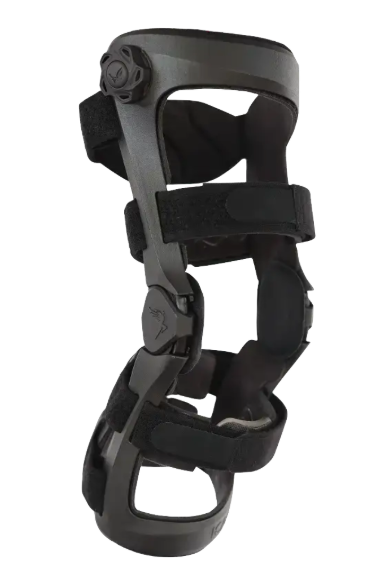
The Ascender by Icarus Medical
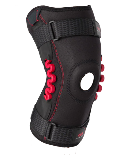
NRG Spring Knee
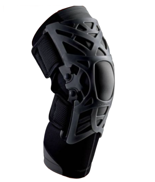
Donjoy Reaction Knee Brace
In the existing commercial market, there are two options for individuals experiencing knee pain: a fully passive element, such as a compressive sleeve, or an expensive, inaccessible active brace. Many medical braces are also only accessible through insurance, potentially alienating a vulnerable customer base. Our solution aims to combine the benefits of both worlds, active and passive elements, while maintaining affordability.
CONCEPT DEVELOPMENT
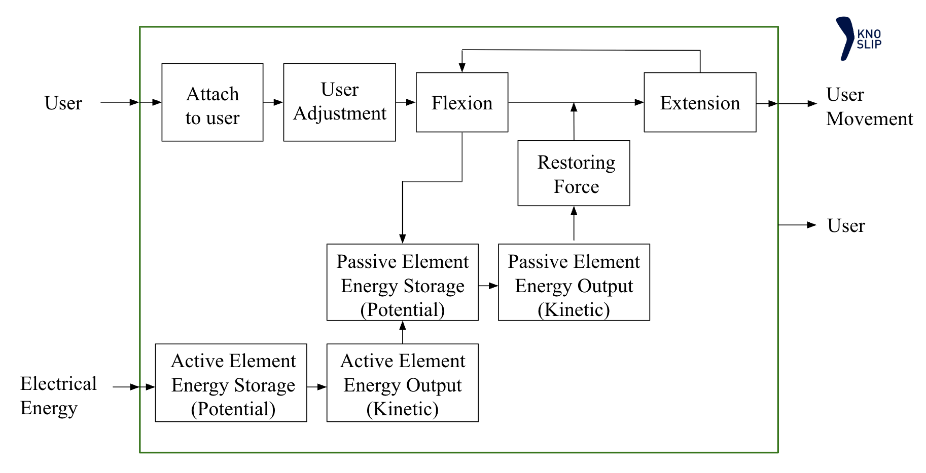
Functional Diagram
Active & Passive Element Selection
Based on prior art, the team focused on three potential passive elements (left): pure compression, elastic band, and spring, and active elements (right): pulley system, hydraulics, and linear actuator. The passive and active elements were then selected using a Pugh matrix, examining crucial design considerations such as comfort, weight, cost, and more.
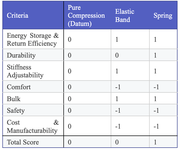
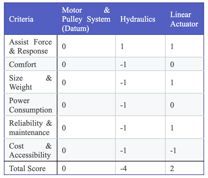
According to our Pugh matrices, a spring/linear actuator combination is the best solution for our knee brace. Our solution includes rigid bracing for load redistribution, a spring serving as our energy-storage element, and a linear actuator for additional support. The addition of padding and foam inside the bracing ensures comfort and fit, along with velcro strapping for adjustability.
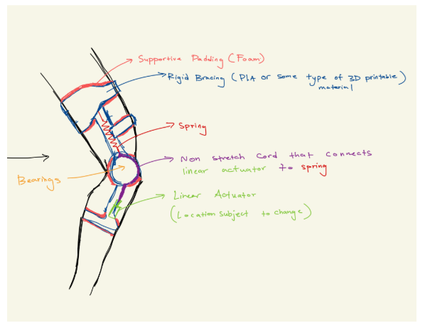
Design Sketch
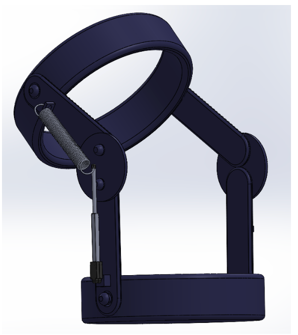
Conceptual 3D Model
Material Selection
For material selection, the team considered 3D-printable plastics for the rigid bracing, primarily TPU, PLA, and ABS. Ultimately, the team selected ABS for its superior strength and durability over PLA.
DESIGN PROCESS
First Design Iteration
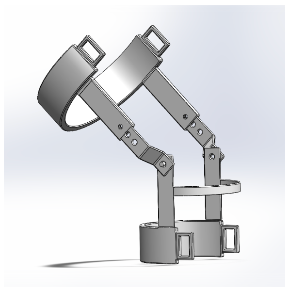
Initial CAD Design
The first design included three separate components: the thigh, hinge, and calf. On both the thigh and calf components, there are openings for the velcro straps. There are holes along the thigh and hinge, allowing the thigh component to sit lower or higher on the leg with pins. As such, the brace can fit a wide range of body types.
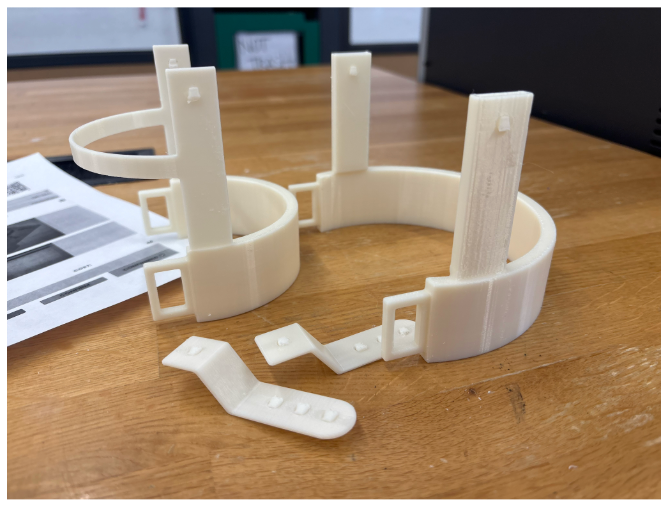
First Print
After assessing the first print, there major design changes to address structural weaknesses and reinforce connections along the brace, leading to our second design iteration. In the first design, the hinge would slide into the thigh component like a sleeve. However, this mechanism compromises the wall thickness of the thigh component, requiring a hollow and thin cross-section. As a result, the sleeve design was abandoned in future iterations. In addition, there were concerns about whether the velcro openings could withstand greater tension since they were not fully incorporated into the bracing.
Second Design Iteration
In the second design, the brace had a more uniform wall thickness and fillets to reduce stress concentrations. Instead of the sleeve connection for the thigh and hinge, the components now sat on top of each other. The velcro openings were also fully incorporated into the circular band of the thigh and calf.
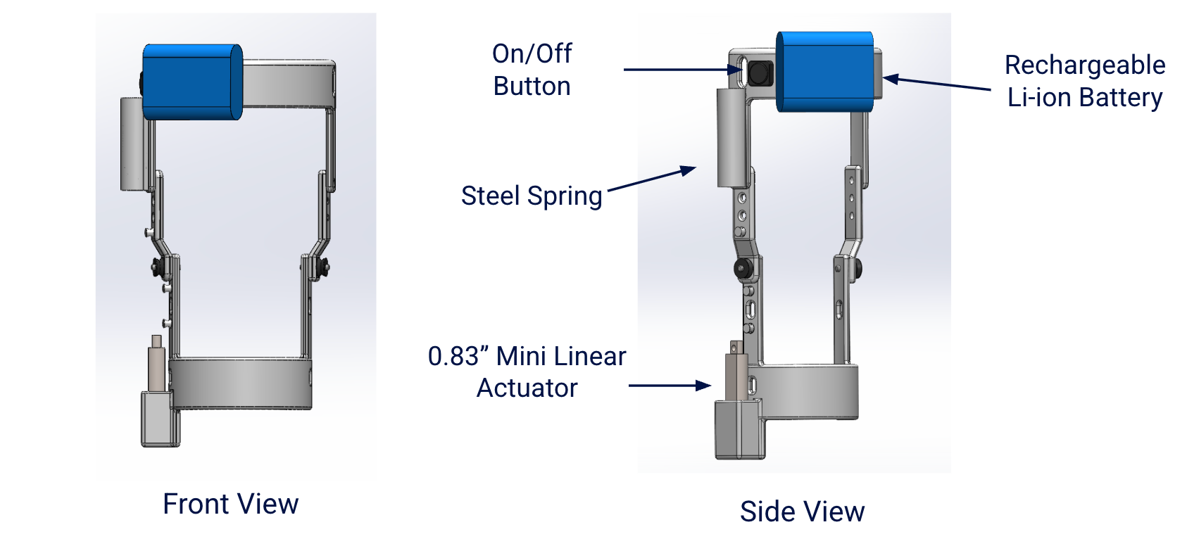
This design includes the final placement of the passive and active elements. The spring, rechargeable Li-ion battery, and button are placed on the thigh. At the hinge/calf connection, there is a set of bearings for smooth bending of the knee. The linear actuator sits at the very bottom of the calf in its own casing. There are eyelets along the bracing to guide the Paracord from the spring down to the linear actuator.
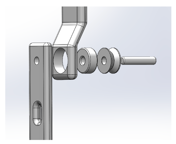
Hing/Calf Connection & Mechanism
Diving deeper into the hinge/calf connection, there is also a pulley attached on the outside. The pulley's diameter displaces the spring (extension) when the leg bends, converting mechanical energy to spring energy for release. When the leg begins to extend, the resulting spring force assists in the motion, serving as the main passive mechanism.
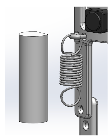
Spring & U-bolt
The spring is attached to the thigh with a steel U-bolt. A removable protective cover was made for the steel spring to prevent pinching and damage. The user can switch out the spring for different stiffnesses depending on their needs.
How It Works
The linear actuator is originally at its extended position. When the knee flexes, the tension in the Paracord increases because of the pulley, stretching the spring. When the knee extends, the tension is released and the spring returns to its initial position, using the restoring force for motion assistance. For the sit-to-stand feature, the linear actuator is now retracted with the click of a button, creating tension by pulling the spring. The tension pulls the thigh component upwards and into a vertical position.
Design Challenges
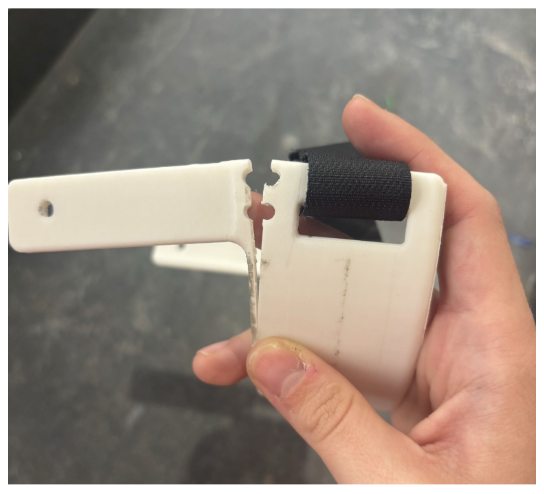
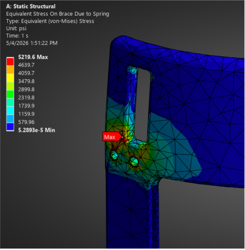
In the second print, the U-bolt area was the most vulnerable to high spring loading. The thigh component experienced a catastrophic failure at that region. As such, the team decided to move the U-bolt inward from the edge and use a lower-rated extension spring, 50 lb-f to 15 lb-f. However, an FEA simulation shows that with 100% infill, our design can theoretically withstand the 50 lb-f without plastic deformation.
FABRICATION
The rigid bracing was entirely fabricated in-house using the ABS printers available in the NYU Tandon MakerSpace and the RDT laboratory (Stratasys F170 & Bambu). The velcro straps, foam, and non-slip fabric were stitched and cut in-house, also in the MakerSpace. The spring, linear actuator, Paracord, and other electronic components were purchased from third parties.
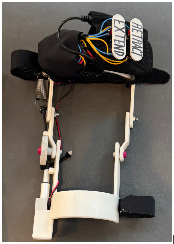
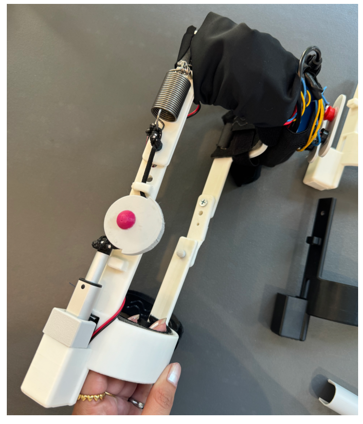
During manufacturing, multiple prints failed due to malfunctions or improper tolerancing. It was incredibly difficult to adjust the tolerance for different ABS printers, and in the end, most holes for pins were drilled. The majority of prints had defects, for instance, being stringy, non-uniform, and in general, deformed. A significant portion of the fabrication process was spent reprinting components.
Bill of Materials
Testing
One team member wore the prototype for 30 minutes to evaluate user comfort and brace stability during daily movement. Feedback from this testing indicated that the brace remained comfortable for long durations without significantly restricting mobility. The lower brace section maintained secure contact with the leg during use. While the upper brace section exhibited slight separation from the thigh during movement, resulting in a looser fit than intended.
CONCLUSION & FUTURE WORK
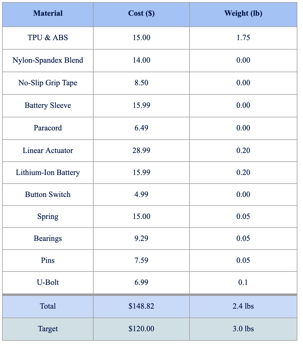
Overall, the prototype successfully demonstrated functional integration of passive and active components, showing that electrical and mechanical systems can work together to assist knee motion. The prototype met key target specifications such weighing less than 3 lbs and remaining cost-effective. In the future, the team would explore other manufacturing processes like injection moulding or explore composite materials (e.g., carbon fibre) for greater durability.
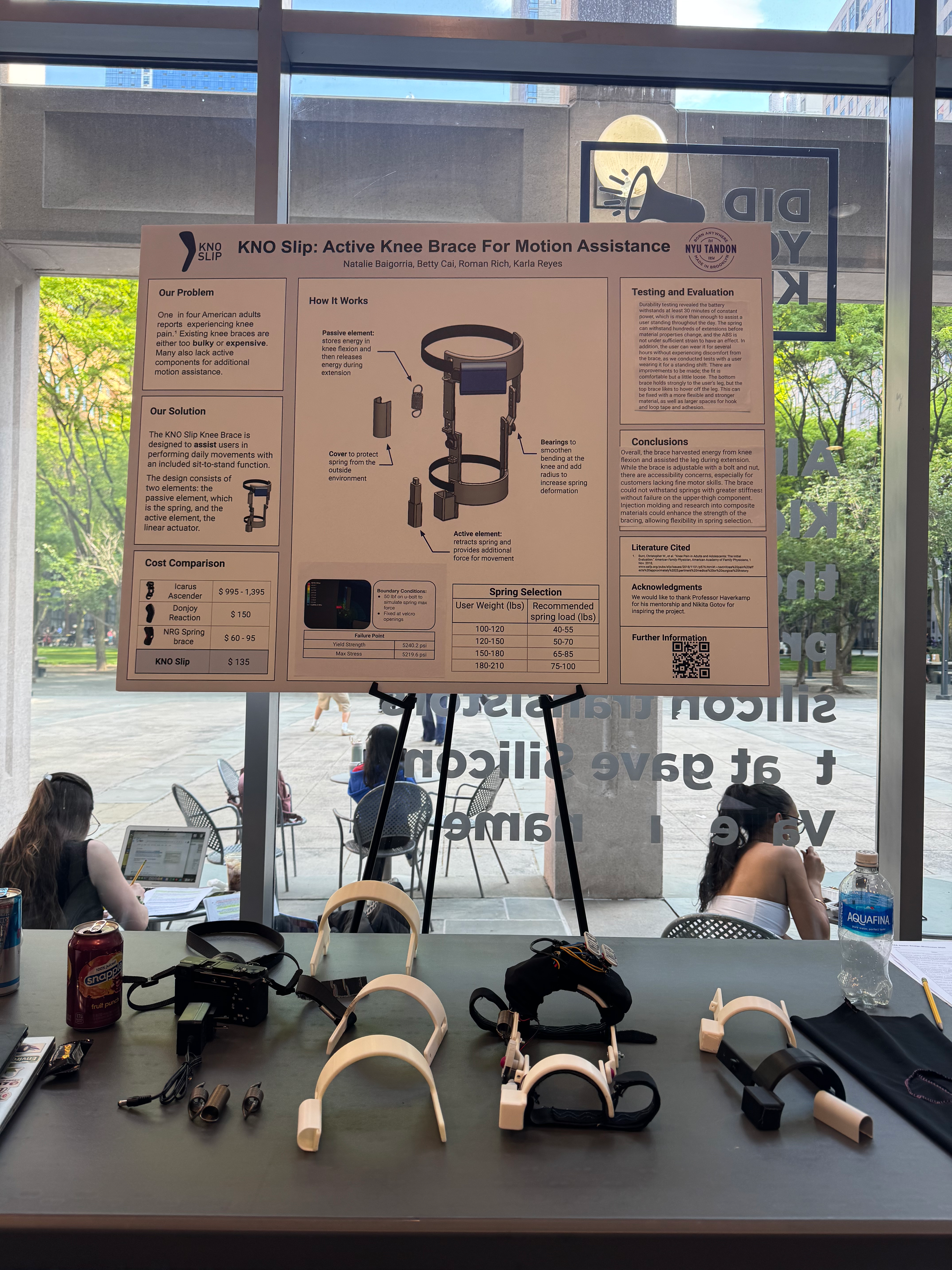
FURTHER INFORMATION
The complete design report can be accessible here: